Evaluating Bus-Topology and IP-Multiplexing Architecture in Factory Security Systems: A Technical Guide for Commercial Alarm Distributors and System Integrators
The panel you choose for a 40,000 m² manufacturing complex is not the same decision as choosing one for a chain of retail stores. Factory environments impose electrical, topological, and operational constraints that expose every weakness in an alarm system’s underlying architecture — and those weaknesses become your warranty liability, your unbillable truck rolls, and your lost renewal contracts.
This guide is written for commercial alarm distributors, security integrators, and procurement managers who are responsible for designing or sourcing intrusion alarm infrastructure for large-scale industrial and manufacturing facilities. It covers the real engineering tradeoffs involved in selecting between traditional analogue wiring, addressable RS-485 bus topology, and modern IP-multiplexed architectures — and explains how that hardware decision directly impacts your total cost of deployment, monitoring center compatibility, and long-term service margin.
The short answer, before we go deeper: in any factory deployment beyond 3,000 m² with multiple production zones, a flat analogue system will fail you. The question is not whether to adopt bus or IP architecture — it is how to layer them correctly.
1. Architectural Challenges of Intrusion Alarm Systems in Modern Factory Environments
Electromagnetic Interference (EMI) and Signal Attenuation in Manufacturing Zones
Manufacturing floors are electrically hostile environments. Variable frequency drives (VFDs) used in conveyor motors and CNC spindles generate broadband conducted noise across a wide spectrum — often 10 kHz to 30 MHz — that couples directly into unshielded signal cables running parallel to power conduit. Heavy industrial switchgear produces inductive transients during switching events that can induce voltage spikes of 50–200 V on adjacent low-voltage control wiring. Even large fluorescent lighting banks create capacitive coupling at 50/60 Hz harmonics.
For an alarm data bus, these interference sources translate into corrupted data packets, ghost zone triggers, and spontaneous panel resets. A traditional analogue zone loop has essentially zero noise immunity: any induced voltage above the panel’s detection threshold registers as an alarm event. Installers routinely encounter “phantom alarms” on production-floor zones that trace back to a VFD that started up on a nearby production line — not to an intruder.
The practical consequence for distributors: your installer spends half a day troubleshooting a ghost alarm in a client’s stamping plant, finds nothing, leaves, and gets called back the next morning. That pattern erodes the client relationship and destroys service margins.
RS-485 differential signaling partially addresses this. Because the receiver responds only to the voltage difference between two conductors rather than the absolute voltage of either, common-mode noise injected equally on both wires cancels out. In practice, this provides 20–40 dB of common-mode noise rejection compared to single-ended analogue circuits — sufficient for most light-industrial environments. However, RS-485 is not a complete solution in heavy manufacturing: very high-frequency noise components (from VFD carrier frequencies above 10 kHz) can still corrupt data frames if cable routing is poor or if cable lengths approach the protocol’s electrical limits.
Fiber-optic Ethernet media, used as the transport layer for IP-multiplexed architectures, eliminates conducted electromagnetic interference entirely. Fiber has no conductors to act as antennas. This is why in welding bays, high-voltage switchgear rooms, and chemical processing zones, fiber-backed IP expansion modules are the only architecture that consistently performs without false alarm filtering workarounds.
Distance Limitations: Overcoming the 1 km+ Bus Boundary Without Adding Latency
The EIA/TIA RS-485 standard specifies a maximum cable length of 1,200 m at 100 kbps with a terminated network. In commercial alarm panel implementations — where bus speeds are typically 9,600 to 38,400 baud and cable capacitance is the primary constraint — the real-world limit without repeaters is usually 800–1,000 m in well-installed systems, and significantly less (sometimes under 400 m) in environments with higher cable capacitance or improper termination.
For a factory with perimeter fence lines, outdoor storage compounds, or buildings separated by 300–500 m gaps, this distance limit is not theoretical — it is a hard deployment barrier. The common field failure mode is intermittent zone offline errors at the most distant nodes. These do not appear during commissioning (when the bus is freshly wired and temperatures are stable) but emerge over the first two seasons as cable insulation absorbs moisture and resistance increases.
Line repeaters extend the physical RS-485 bus by regenerating the signal and resetting the distance counter. A repeater installed at the 900 m mark allows the bus to continue for another 1,200 m. However, each repeater adds a fixed latency of 1–3 ms per hop, and every additional repeater introduces a maintenance point. In multi-building factory deployments where the panel is in a central security room, a daisy-chain approach with three or four repeaters across 3,500 m of perimeter cable is technically feasible but operationally fragile: a single cable cut isolates everything downstream of the break.
This is where IP aggregation becomes structurally superior. By placing a local RS-485 bus controller (a zone expander or IP module) in each building or compound section, and backhauling via the factory’s existing fiber LAN to the main control panel, you eliminate the distance constraint entirely. The bus runs within each building — staying well under 200–400 m — and the aggregation layer uses TCP/IP over fiber, which is effectively unlimited in distance. Alarm panel to fiber converter to LAN switch to IP module to local bus: this is the architecture that scales.
Power Distribution Dilemmas: Resolving Bus Voltage Drops in High-Density Detector Deployments
Voltage drop on alarm bus wiring is the most commonly underestimated engineering problem in large factory deployments, and it surfaces at the worst possible time: during a full alarm load when every detector on the loop is drawing peak current simultaneously.
The governing formula is:
$$V_{\text{drop}} = 2 \times I \times R \times L$$
Where:
- $I$ = aggregate standby or alarm current draw of all nodes on the loop (in amperes)
- $R$ = resistance per meter of the conductor ($\Omega/\text{m}$), determined by wire gauge
- $L$ = physical distance to the furthest node (in meters)
- The factor of 2 accounts for the outgoing and return conductor
For 22 AWG stranded wire (commonly specified in alarm installation), the conductor resistance is approximately $0.054\ \Omega/\text{m}$. For 18 AWG wire, this drops to $0.021\ \Omega/\text{m}$.
Worked Example:
A factory bus loop with 48 addressable nodes, each drawing 12 mA in standby (8 mA) and alarm (12 mA per node in alarm state), extending 650 m to the furthest zone module.
- Total alarm current: $48 \text{ nodes} \times 0.012\text{ A} = 0.576\text{ A}$
- Using 22 AWG: $V_{\text{drop}} = 2 \times 0.576 \times 0.054 \times 650 = 40.435\text{ V}$
This calculation immediately reveals the problem: a 12 V DC bus system cannot sustain a $40.435\text{ V}$ voltage drop. In practice, nodes begin failing to communicate when their local supply voltage drops below 10.5 V DC — the minimum operating threshold for most addressable bus transceivers. With a nominal 13.8 V DC supply at the panel, only 3.3 V of headroom is available before node failures begin.
The engineering resolution is not simply to “use thicker wire.” The correct approach is to:
- Upgrade to 18 AWG or 16 AWG cable on runs exceeding 200 m (reduces voltage drop by 60–70%)
- Distribute power injection points — install auxiliary power supplies at the midpoint or end of long loops
- Segment high-density zones into shorter sub-loops using bus expanders rather than stretching a single loop across the entire factory
Ignoring this during design phase and discovering it during commissioning is one of the primary reasons factory security projects run over budget. The rework cost of pulling heavier cable through conduit in an operating facility is disproportionately expensive.
2. Bus-Topology vs. IP-Multiplexing: Designing a Resilient Burglar Alarm Factory Network
Comparing Addressable RS-485 and CAN Bus Architectures for Industrial Control Panels
Both RS-485 and CAN bus (Controller Area Network) use differential signaling and operate effectively in high-noise environments, but their fault-handling mechanics differ in ways that matter for large alarm networks.
RS-485 in alarm panel implementations is typically a polled master-slave protocol: the control panel sequentially queries each node on the bus and awaits a response within a defined timeout window. This architecture is simple, highly deterministic, and well-understood by alarm panel firmware designers. Its vulnerability is collision handling: if a node malfunctions and begins transmitting continuously (a “babbling idiot” failure), it can corrupt the entire bus segment until isolated. Standard RS-485 alarm bus designs do not have hardware arbitration — the panel firmware must detect the anomaly and flag the segment.
CAN bus uses hardware-level arbitration and a built-in error frame mechanism. Every node can detect transmission errors, and a node experiencing persistent errors enters a passive or bus-off state automatically without firmware intervention. This makes CAN bus significantly more robust in environments with intermittent electrical faults — which is exactly the condition present in manufacturing facilities. CAN bus also supports transmission speeds up to 1 Mbit/s at short distances (compared to RS-485’s practical ceiling of about 100 kbps at 1 km), allowing higher polling throughput on dense node networks.
The tradeoff: CAN bus controller hardware is more expensive, less universally available in alarm panel designs, and requires more sophisticated network termination discipline. RS-485 remains the dominant physical layer in commercial burglar alarm control panels because it offers a reasonable balance of cost, distance, noise immunity, and ecosystem compatibility. Most addressable alarm panels on the market — including Athenalarm’s commercial intrusion platforms — implement RS-485 as the primary field bus, with IP-based expansion modules used to bridge multiple loops or overcome distance barriers.
Hybrid Network Design: Utilizing IP Modules for Zone Aggregation and Centralized Management
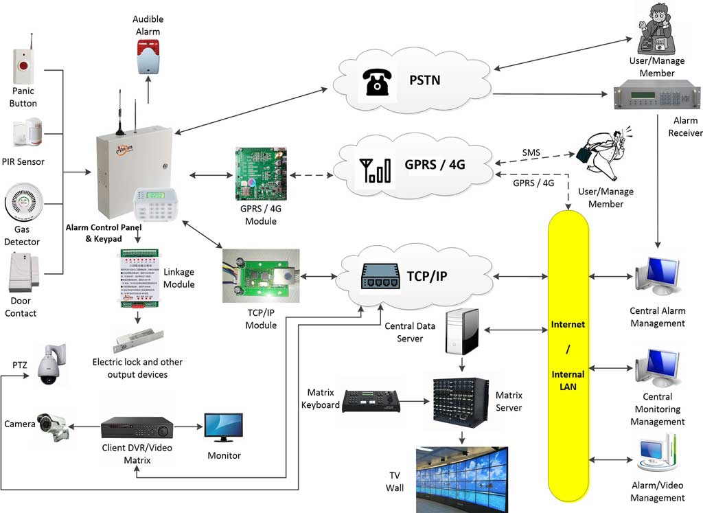
The architecture that consistently performs across large factory deployments is a layered hybrid: local RS-485 bus loops within each building or zone, aggregated at IP-based expander modules, with TCP/IP backhaul to the central control panel via the factory’s LAN or fiber infrastructure.

This design solves three constraints simultaneously:
- Distance: Each local RS-485 segment stays within 200–400 m — well within reliable operating parameters. The IP layer carries data across any distance.
- Zone capacity: A single control panel may support 8–16 RS-485 bus addresses directly. By deploying IP zone expansion modules, each of which runs its own local RS-485 sub-bus, a single master panel can effectively manage hundreds or thousands of zones distributed across a multi-building campus.
- Fault isolation: A cable cut or short circuit on the RS-485 segment in Building C does not affect the status of zones in Buildings A, B, or D. IP connectivity to each building’s expander module remains independent.
The practical deployment sequence: the installer commissions each building’s local RS-485 loop first, verifies node addressing and signal integrity, then connects the IP module to the factory LAN. The main panel sees each building as a high-capacity logical expansion rather than a physical wire run. Central station monitoring integrates at the panel level via SIA DC-09 over IP — the monitoring center sees the same alarm event stream regardless of whether the originating detector is 50 m or 2,000 m from the master panel.
One operational caveat: this architecture depends on the reliability of the factory’s LAN infrastructure. In facilities where the IT department controls the network and security personnel do not, access policy conflicts can create deployment obstacles. It is worth establishing, before the contract is signed, whether the security system will use the factory’s production network, a dedicated security VLAN, or a separate physical network. Shared production networks introduce switch configuration dependencies that become a long-term support liability.
Technical Data Matrix: Communication Architecture Comparison
| Technical Parameter | Traditional Analogue Zones | Industrial RS-485 Bus | IP-Multiplexed Architecture |
|---|---|---|---|
| Maximum Topological Distance | ~300 m (loop resistance limit) | Up to 1,200 m per segment without repeaters | Unlimited via LAN/Fiber backbone |
| Max Node / Zone Capacity | 1 zone per hardwired run | 128–256 nodes per loop (panel dependent) | Thousands of zones via IP aggregators |
| Noise Immunity (EMI/RFI) | Poor — susceptible to induced voltage | High — differential signaling rejects common-mode noise | Very High — isolated Ethernet or fiber media |
| Fail-Safe Redundancy | None — single conductor break disables zone | Loop isolation modules — contain short circuits to segment | Dual-path / Spanning Tree Protocol (STP) |
| Diagnostic Capability | Binary: open or short circuit only | Node-level polling: address, status, tamper, power | Packet-level telemetry, real-time IP ping, heartbeat monitoring |
| Typical Commissioning Time (200-zone factory) | High — individual zone termination and labeling | Moderate — bus addressing and signal verification | Low to Moderate — IP configuration adds initial complexity, reduces long-term service time |
| False Alarm Vulnerability from EMI | Very High | Moderate (shield + grounding discipline required) | Low (fiber segments immune; IP segments isolated from field wiring) |
| TCO at 10 Years | High — rip-and-replace likely at expansion | Medium — modular expansion within bus capacity | Low — software-addressable expansion, no new wiring for capacity increases |
3. Protocol Deep-Dive: Ensuring Seamless Central Station Monitoring and System Integration
Transitioning from PSTN Contact ID to SIA DC-09 Over IP in Commercial Security
Contact ID, developed by Ademco in the early 1990s, transmits alarm events as dual-tone multi-frequency (DTMF) audio signals over standard telephone lines. Each event is encoded as a burst of audio tones representing account number, event qualifier, event code, partition number, and zone number — typically transmitting at 103 ms per digit with gaps between groups. A complete alarm event transmission takes 3–8 seconds over a single PSTN connection.
For a factory security system that may generate burst alarm events across dozens of zones during a perimeter intrusion — access control triggers, beam detector activations, motion sensor cascades — this bandwidth is inadequate. Contact ID was designed for residential and small commercial panels reporting a handful of events. It was never designed for industrial alarm networks reporting 50 simultaneous zone states.
SIA DC-09 (SIA Protocol DC-09-2013 and later revisions) is a native IP reporting protocol that transmits structured data packets directly over TCP or UDP connections to a central station receiver. Each packet is a formatted ASCII string or binary frame containing account identifier, timestamp (milliseconds resolution), event type, zone description, partition, and optional extended data fields. A single TCP connection can carry multiple alarm events without the sequential DTMF handshaking bottleneck of Contact ID.
Key technical distinctions relevant to factory deployments:
- Encryption: SIA DC-09 natively supports AES-256 encryption of the event payload. Contact ID transmits in the clear over analog phone lines.
- Acknowledgment: DC-09 includes receiver acknowledgment of each transmitted event, enabling the panel to confirm delivery and retry on failure. DTMF Contact ID has no delivery confirmation at the protocol level.
- Zone descriptions: DC-09 supports free-text zone labels — “North Perimeter Gate 3 PIR” rather than zone number 047. For a 500-zone factory system, this difference in alarm management at the monitoring center is significant.
- Dual-path: DC-09 can operate simultaneously over two independent IP paths (primary corporate WAN and backup cellular), with the receiver logging which path delivered each event. Contact ID over IP converters generally do not support true dual-path at the protocol level.
The migration challenge for distributors serving markets with established Contact ID infrastructure: monitoring centers may require firmware updates to their receivers to handle DC-09 correctly, and some legacy Manitou, DICE, or SurGard receiver configurations require parameter adjustments to process the DC-09 event format. Verify receiver compatibility before quoting an IP-reporting project.
Modbus and SDK Integration: Linking Factory Intrusion Alarms with SCADA, BMS, and CCTV Platforms
Larger manufacturing facilities increasingly require intrusion alarm systems to integrate with their existing operational technology infrastructure: SCADA platforms monitoring process controls, Building Management Systems (BMS) controlling HVAC and access, and VMS (Video Management Systems) driving PTZ cameras and recording.
This integration work is where many alarm distributors either win high-value contracts or lose them to competitors with better technical depth.

Modbus-TCP Integration with SCADA
Modern alarm control panels that expose a Modbus-TCP interface allow SCADA systems to read zone states, alarm conditions, and system health data as register values. A typical mapping might assign zone status registers starting at holding register 40001, with each register bit representing a zone’s alarm/normal state. The SCADA system polls the panel at configurable intervals (typically 1–5 seconds) and can trigger process responses — halting conveyor belt operations, activating emergency lighting, locking blast doors — based on alarm panel input states. For chemical processing or hazardous material storage facilities, this integration is not a feature request; it is a site safety requirement.
ONVIF Profile S for Camera Integration
When a perimeter beam detector activates at the factory’s east fence line, the alarm panel should immediately direct the nearest PTZ camera to a preset position covering that section — and begin recording to the monitoring center’s cloud. This is implemented via ONVIF Profile S, the standardized protocol for controlling PTZ cameras and triggering recording actions across multi-vendor VMS platforms. The alarm panel (or its IP communications module) issues ONVIF commands specifying the camera’s network address, the target PTZ preset number, and a recording trigger. This eliminates the need for proprietary video-alarm integration middleware.
Native SDK and REST API
Some alarm panel manufacturers — including the Athenalarm platform — provide native SDK libraries or REST API endpoints that allow custom integration work without being constrained by the Modbus register mapping or ONVIF command set. For integrators bidding on smart factory or government security contracts requiring unified command dashboards, SDK access is the difference between winning the contract and losing it to a competitor whose panel can be embedded into the client’s PSIM (Physical Security Information Management) platform.
The integration complexity should be factored into project quotes. A Modbus or ONVIF integration that looks straightforward in the product datasheet typically requires 8–20 hours of configuration, testing, and troubleshooting in the field — especially when the factory’s IT team has strict firewall policies that block the necessary port ranges by default.
Dual-Path Communication (GPRS/LTE + LAN) for Mission-Critical Factory Redundancy
A factory security system that relies on a single communication path — whether fiber, copper LAN, or cellular — has an architectural single point of failure that any serious client should reject during system review.
The standard for mission-critical reporting is dual-path with automatic failover and independent path health monitoring. In practice:
- Primary path: TCP/IP via the factory’s corporate WAN or dedicated security LAN, reporting via SIA DC-09 to the central station receiver.
- Secondary path: 4G LTE via an integrated cellular communicator module using a private APN (if the client’s IT security policy requires isolation from the public cellular internet) or a standard carrier SIM. The panel transmits heartbeat signals to the receiver on both paths simultaneously at defined polling intervals — typically every 30–90 seconds.
The receiver monitors both paths continuously. If a primary path heartbeat is missed for a configured timeout window (commonly $3 \times \text{polling interval}$, so 90–270 seconds depending on supervision level), the receiver logs a primary path failure and continues accepting events on the secondary path. When primary path connectivity restores, automatic fallback occurs without manual intervention.
For factory sites, the relevant failure scenarios are:
- Fiber cut during construction activity on adjacent property — the most common cause of primary path outages
- Corporate WAN gateway failure during IT maintenance windows (which factories often schedule late-night or weekend, precisely when the facility is unmanned and alarm risk is elevated)
- Power outage affecting network infrastructure — factory UPS systems may not include LAN switches in their protected load groups
The 4G cellular communicator acts as a continuous insurance policy. However, cellular reliability introduces its own dependencies: SIM cards require active data plans with monitoring center whitelisted IP addresses. Carriers occasionally perform APN reconfiguration that disrupts static IP allocations. In markets where 2G/3G networks are being decommissioned (a process that has affected alarm communicators in Australia, Japan, and parts of Europe since 2019), panels using legacy GPRS modules have experienced undetected communication failures. Specify 4G LTE Category M1 or Category 1 cellular modules as the minimum standard for any new factory deployment.

4. Engineering Blueprint: Deployment and Commissioning Protocols for Factory Security Systems
Zone Segmentation Strategies: Isolating Hazardous Production Lines from Warehouse Perimeters
A factory of any significant scale is not a single security zone. It is a collection of distinct operational areas with different risk profiles, access schedules, and detector technology requirements — and they should be managed as independent security partitions within a single enterprise alarm panel.
Consider a typical medium-sized manufacturing complex: welding and fabrication bays with high EMI and temperature extremes; clean rooms or quality control areas with strict access control; a warehouse and dispatch area with regular out-of-hours logistics activity; and an executive office building with standard commercial security requirements. These areas are armed, disarmed, and monitored on completely different schedules — and a false alarm generated in the welding bay should never trigger a full-facility response that locks out the night-shift workers in the warehouse.
Partition design achieves this. Each area is assigned to an independent partition with its own arming/disarming schedule, its own keypad or credential reader, and its own alarm response profile. The master panel integrates all partitions into a unified event log for the monitoring center while maintaining operational independence for each area.
The engineering discipline here is in zone assignment during the design phase, not during commissioning. Experienced integrators create a zone partition map before a single cable is pulled — documenting which detectors belong to which partition, what the arming authority level is for each, and what the detector type matrix is for each environment. Changing partition boundaries after installation, because the factory manager decided the quality control lab should have its own schedule, means reprogramming and potentially re-labeling dozens of zones. Prevention is orders of magnitude cheaper than remediation.
Anti-Interference Wiring Techniques: Correct Shielding, Grounding, and Use of Bus Isolators
Field wiring quality in a factory alarm installation determines system reliability more than any specification in a product datasheet. The following rules are non-negotiable in high-EMI environments:
- Single-end shield grounding: Shielded twisted-pair cable (required on all RS-485 bus runs in factory environments) must have the shield conductor connected to earth ground at the control panel end only. If the shield is grounded at both ends — a common mistake by installers more familiar with residential wiring — a ground loop is formed. Ground loops allow 50/60 Hz power current to flow through the shield, creating a continuous noise source that degrades signal integrity. Single-end grounding eliminates the loop while still providing electrostatic shielding.
- Physical separation from power wiring: RS-485 alarm bus cables should not share conduit with 230 V or 415 V power wiring. Minimum physical separation is 150 mm in parallel runs, with 90-degree crossings preferred over parallel crossings when separation cannot be maintained. In factories where cable management is not prioritized during construction, this is a constant negotiation with the electrical contractor.
- Bus isolation module placement: Bus isolation modules detect short-circuit conditions on their downstream segment and electronically disconnect the faulted section from the rest of the bus within microseconds — before the fault can corrupt data on adjacent segments. Strategic placement of isolation modules is determined by the physical vulnerability of cable runs: outdoor perimeter cables, runs through vehicle access doors (susceptible to cable crush damage), and segments running through high-risk EMI zones all warrant isolation module protection.
A practical rule of thumb: install a bus isolation module at the entry point to any outdoor cable run, and at any point where two or more building-crossing runs connect to a common bus segment. The cost of an isolation module (typically $15–40 USD per unit at distributor pricing) is trivially small compared to the diagnostic time and potential rework if a single outdoor cable fault takes down 40% of a factory’s internal detection network.
Troubleshooting Framework: Diagnostic Protocols for Distant Loops
Factory security service calls for bus or node failures follow a predictable diagnostic flow. Presenting field engineers with a structured decision framework — rather than unstructured troubleshooting — reduces average diagnosis time and improves first-visit resolution rates.
[Field Failure: Distant Node Offline]
              │
              ▼
  Step 1: Measure DC voltage at the affected node terminal
              │
  ┌───────────┴───────────┐
  ▼                       ▼
Voltage < 10.5V DC     Voltage ≥ 11.5V DC
  │                       │
  ▼                       ▼
→ Check wire gauge         → Measure AC ripple voltage (EMI noise)
→ Measure current draw     → Check bus termination resistor (120Ω at end of line)
→ Install line repeater    → Verify node address — duplicate addresses cause
→ Verify ground loops        silent conflicts
→ Consider power injector  → Check shield continuity and grounding point

  [Voltage 10.5–11.5V: Marginal Zone]
              │
              ▼
→ Monitor under full-load alarm condition
→ Upgrade wire gauge on next scheduled maintenance
→ Flag for power injector installation within 12 months
This framework assumes the node hardware is functional. Before beginning any electrical measurement, verify the node is not in tamper condition (cover removed), confirm the bus address is correctly set, and confirm the panel firmware has recognized the node historically. Panel event logs showing a node intermittently online and offline over several weeks are a signature of marginal voltage — not node hardware failure.
5. Commercial Value for Global Alarm Distributors and B2B Importers
Inventory Optimization: How Modular Burglar Alarm Panels Reduce SKU Redundancy for Distributors
The economics of distributing alarm equipment for industrial and commercial markets are driven heavily by inventory strategy. A distributor stocking discrete products — a 16-zone panel for small clients, a 64-zone panel for mid-size clients, a separate 256-zone panel for large industrial sites — is carrying three separate product lines with three separate support burdens, three separate firmware update cycles, and three separate sets of compatible peripherals.
Modular panel architecture resolves this. A single core control panel platform — with a base zone capacity of, say, 16 zones — combined with RS-485 bus expansion boards, IP zone aggregators, and cellular communication modules, can fulfill a 16-zone retail deployment and a 400-zone multi-building factory deployment from the same master SKU. The distributor stocks core panels, expansion modules, and communication modules rather than discrete products at each capacity tier.
The inventory financial impact is measurable: fewer SKUs means lower minimum order quantities per line item, faster stock turnover, and reduced risk of holding obsolete product when a manufacturer updates a capacity tier. For distributors serving diverse geographic markets — where a project in West Africa might be a 30-zone standalone installation and a project in Eastern Europe might be a 200-zone industrial complex — modular systems allow a single inventory pool to serve both without overstocking either.
The Athenalarm product platform is architected around this principle: the same base panel platform supports small commercial deployments through field-expansion to large industrial configurations without requiring the distributor or integrator to retrain on a different product family or maintain separate spare parts inventories.
Lowering Total Cost of Ownership (TCO) Through Backward Compatibility and System Scalability
The most persuasive argument in any large commercial security project is not upfront cost — it is 10-year TCO. Procurement managers at manufacturing companies understand that a security system will be in service for 8–15 years, and a system that requires full replacement every 5 years because of protocol obsolescence or discontinued hardware is not a security investment; it is a recurring capital expenditure.
TCO analysis for factory intrusion systems should account for:
- Expansion costs: If a factory adds a new production building in year 4, can the existing alarm panel be expanded with a bus module and additional detectors — or does it require a new panel? Open-architecture RS-485 bus systems with addressable expansion capacity allow incremental growth without system replacement.
- Protocol longevity: Systems using standardized open protocols (RS-485, SIA DC-09, Modbus-TCP) are not dependent on a single manufacturer’s survival or product roadmap. If a bus expansion module manufacturer discontinues a product, a compatible replacement from another supplier that conforms to the same RS-485 signaling standard and panel addressing protocol can substitute. Proprietary closed-protocol systems create a single-supplier dependency that is a real commercial risk over a 10-year horizon.
- Firmware upgrade dependency: Closed-ecosystem panels that require manufacturer-specific firmware updates to maintain functionality — or to maintain compatibility with a central monitoring platform — introduce an ongoing relationship dependency. Each update cycle is an opportunity for a manufacturer to change pricing, discontinue support for older hardware, or introduce compatibility breaks. Distributors who have built their service portfolio around such systems have experienced exactly this pressure when manufacturers restructure their channel programs.
- Monitoring center compatibility: A factory security system that reports via standard SIA DC-09 over IP can transition to a different monitoring center without hardware replacement — a meaningful bargaining tool for the building owner when the monitoring contract comes up for renewal. Proprietary reporting protocols lock the client into a specific monitoring center, which reduces competitive pressure on the monitoring rate.
Taken together, these factors consistently favor open-architecture modular systems in 10-year TCO models, even when the upfront hardware cost is modestly higher than closed-ecosystem alternatives.
Technical FAQ for Industrial Alarm Procurement Managers
Q1: Can an RS-485 bus-topology alarm system handle video verification integration?
Yes, but video is handled at the IP layer, not the bus layer. The RS-485 bus carries zone alarm events to the control panel. The panel then issues ONVIF Profile S commands or native SDK calls over TCP/IP to direct cameras to preset positions and begin live streaming to the central monitoring station. The two layers operate in parallel and do not interfere with each other. The key design requirement is that the alarm panel’s IP communication module must be able to initiate outbound TCP connections to the VMS or camera management platform — verify firewall rules during system design, not during commissioning.
Q2: How do bus isolation modules protect large-scale industrial factory networks?
A bus isolation module sits in-line on the RS-485 data bus and continuously monitors the line voltage and impedance of its downstream segment. When a short circuit, cable crush, or lightning-induced fault occurs — on an outdoor perimeter run, for example — the module detects the fault condition within milliseconds and electronically opens the downstream circuit, disconnecting the faulted segment from the rest of the bus. The upstream portion of the bus continues operating normally. Without bus isolators, a single outdoor cable fault can take down every node on the entire loop, rendering large sections of a factory’s detection network inoperative until the fault is physically located and repaired.
Q3: Why is SIA DC-09 preferred over Contact ID for modern factory alarm backhaul?
SIA DC-09 is a native IP protocol that transmits structured alarm data directly over Ethernet or cellular connections with AES-256 encryption, millisecond-precision timestamps, and full delivery confirmation. Contact ID was designed for DTMF transmission over analog telephone lines at 1 event per 3–8 seconds — inadequate for factory systems that may generate dozens of simultaneous zone events during a perimeter breach. DC-09 also supports unrestricted text-based zone descriptions (critical for managing 300+ zone systems at a monitoring center) and true dual-path reporting. Contact ID over IP converters exist but introduce an additional translation layer that creates its own compatibility and diagnostic complexity.
Q4: What is the minimum wire gauge recommended for RS-485 bus runs exceeding 300 m in a factory?
18 AWG shielded twisted-pair is the practical minimum for bus runs of 300–800 m in factory environments with moderate current loads. For runs approaching 1,000 m or with node populations exceeding 40 units, 16 AWG reduces voltage drop sufficiently to maintain reliable operation under full alarm load. Regardless of gauge, verify that the calculated voltage at the furthest node under full alarm current draw remains above 10.5 V DC. If the calculation shows marginal headroom, install a power injection point at the midpoint of the run rather than upgrading the cable after installation.
Q5: How does EMI from variable frequency drives affect alarm detector selection for production floor zones?
PIR motion detectors on production floors near VFD-equipped machinery require EMI-hardened models with enhanced RF filtering on their signal outputs. Standard residential or light-commercial PIRs will generate false alarms from induced electrical noise, particularly during motor startup transients. Specify detectors with on-board signal processing that applies frequency filtering, minimum alarm duration thresholds (e.g., 50 ms), and dual-technology (microwave + PIR) confirmation where budget allows. Addressable detectors that report signal strength and tamper status to the panel are strongly preferred in high-EMI environments, as they allow the monitoring center to distinguish electronic interference signatures from genuine motion events.
Engineering Reference: Entity and Protocol Quick-Reference
| Term | Category | Definition |
|---|---|---|
| RS-485 | Physical bus standard | Differential two-wire serial protocol, max 1,200 m at 100 kbps, used as primary field bus in addressable alarm panels |
| SIA DC-09 | Alarm reporting protocol | IP-native alarm transmission protocol with AES-256 encryption and delivery acknowledgment; replaces DTMF Contact ID over IP |
| Contact ID | Legacy alarm protocol | DTMF-based alarm reporting over PSTN lines; widely supported but bandwidth-limited and unencrypted |
| Bus Isolation Module | Hardware protection | In-line RS-485 device that electronically disconnects faulted bus segments to contain short circuits |
| Line Repeater | Signal regeneration | Device that amplifies and retimes RS-485 signals to extend bus runs beyond the 1,200 m electrical limit |
| EOLR | Zone supervision | End-of-Line Resistor; resistor placed at the end of a zone loop to enable continuous supervision of conductor continuity |
| ONVIF Profile S | Camera integration standard | Open standard enabling alarm panels to control PTZ cameras and trigger recording via TCP/IP commands |
| Modbus-TCP | Industrial integration protocol | Ethernet-based extension of Modbus protocol; enables alarm panel zone data to be read by SCADA and BMS platforms |
| Dual-path communicator | Redundancy hardware | Communication module with simultaneous primary IP and secondary cellular reporting, with automatic path failover |
| VFD | EMI source | Variable Frequency Drive; motor speed controller that generates broadband conducted and radiated electromagnetic noise |
| TCO | Business metric | Total Cost of Ownership; 10-year analysis of capital, installation, expansion, service, and replacement costs |
| Private APN | Cellular configuration | Private Access Point Name; dedicated cellular data routing that isolates alarm traffic from public internet |
Athenalarm is a professional burglar alarm manufacturer and commercial security system supplier, providing addressable alarm panels, network alarm monitoring infrastructure, and OEM/ODM development services for global alarm distributors, system integrators, and monitoring center operators. Technical specifications and deployment guidance are available through the Athenalarm technical support portal.