Engineering Specification Guide: Evaluating Commercial Alarm Panel Manufacturers on Bus Line Topology, Multi-Path IP Protocols, and CMS Receiver Interoperability
Selecting a commercial alarm panel manufacturer is not primarily a hardware-price decision. It is an architecture, interoperability, and lifecycle decision.
A panel with more zones, a lower unit price, or a larger enclosure can still become the more expensive choice after deployment if its RS-485 bus is difficult to engineer, its communication path fails unpredictably, its reporting protocol is only partially implemented, or the CMS receiver interprets events differently from the panel.
For distributors, security importers, OEM brand owners, and security system integrators, the more useful procurement question is therefore not which alarm panel has the longest feature list. The real question is whether the manufacturer can provide a documented and testable platform that remains workable from the field device through the alarm panel, communication path, receiver, CMS workflow, integration layer, and future product revisions.
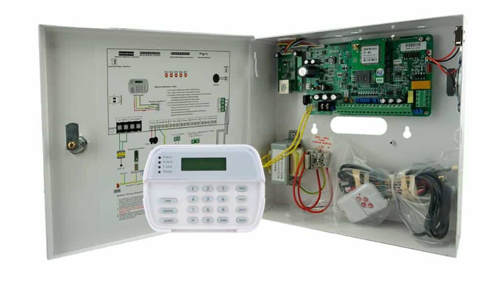
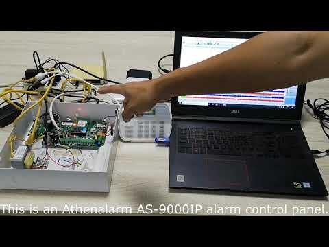
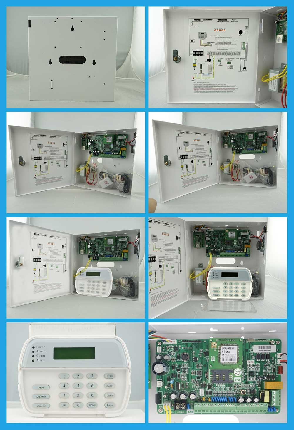
For a practical reference point, see Athenalarm AS-9000 Addressable Intrusion Alarm Control Panel when comparing a published manufacturer platform against the framework below.
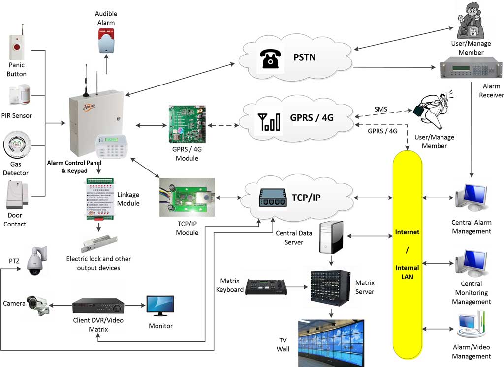
A commercial alarm panel should consequently be evaluated across four connected layers:
| Engineering layer | Primary concern | Evidence to request |
|---|---|---|
| Physical layer | Zones, RS-485, power, protection, expansion | Electrical specifications, installation documentation |
| Communication layer | Ethernet, cellular, PSTN, supervision and failover | Communication specifications, configuration records, test reports |
| Protocol layer | SIA DC-09, Contact ID and proprietary interfaces | Protocol declaration, implementation details, interoperability records |
| Monitoring and integration layer | Receiver, CMS, VMS, access control and APIs | End-to-end integration and field testing |
The significance of this model is that many commercial alarm failures occur between these layers rather than inside a single product.
A panel may detect an intrusion correctly while the monitoring center never receives the event. A communicator may report that an Ethernet link is available while its application session to the receiver is no longer functioning. An RS-485 module may work during commissioning and then become intermittent when voltage drop, cable capacitance, grounding or electromagnetic interference becomes significant.
For a manufacturer, these are engineering problems. For a distributor, they become installation delays, replacement stock, technical support cases, warranty exposure and potentially a fragmented installed base.
This guide therefore treats the manufacturer as an engineering platform rather than a box supplier. The same principle applies whether the project involves a commercial building, logistics facility, industrial site, retail chain, campus, multi-tenant property or a distributed multi-site monitoring architecture. The framework also applies when a distributor is preparing to build a private-label alarm portfolio around an OEM or ODM manufacturer’s platform.
1. Start with Architecture, Not the Datasheet
A commercial intrusion alarm panel should be evaluated as part of a field network.
This sounds obvious, but many procurement exercises still begin with the same three numbers: zone count, unit price and communication interfaces. Those numbers are useful, but they do not describe how the system behaves once hundreds of field devices, long cable runs, multiple communication paths and a central monitoring environment are involved.
A more useful evaluation starts with the physical layer and moves upward.
At the physical layer, ask how zones are implemented, how expansion modules are connected, how power is distributed and how the manufacturer expects long communication runs to be installed. At the communication layer, ask how the panel reaches the monitoring infrastructure and how failure is detected. At the protocol layer, ask what event format is actually transmitted and how it is acknowledged. At the monitoring layer, ask whether the receiver and CMS interpret the event correctly.
This creates an important distinction:
A feature is a product claim. An engineered behavior is a qualification result.
That distinction should shape the entire supplier-audit process.
2. Bus Line Architecture: Where Commercial Scale Begins
The first major hardware question is how the manufacturer expands the alarm system.
Traditional hardwired zones normally use dedicated conductors for individual detector circuits or localized loops. An addressable RS-485 architecture instead allows multiple devices or expansion modules to communicate over a shared bus.
Neither model should automatically be treated as better.
For a small property with short cable runs, conventional hardwired zones may be straightforward to install and maintain. For a large commercial facility with many distributed modules, addressable expansion can provide a more structured way to identify devices and manage system growth. A hybrid architecture can combine local onboard zones, addressable expansion and wireless devices where the site contains different wiring conditions.
| Architecture | Typical wiring model | Expansion strategy | Practical fit |
|---|---|---|---|
| Conventional hardwired | Dedicated circuits | Limited by physical I/O | Small and medium installations |
| Addressable RS-485 | Shared bus | Multiple addressable devices/modules | Commercial and industrial deployments |
| Hybrid | Onboard + bus + wireless | Layered expansion | Mixed and scalable projects |
The important procurement question is therefore not simply whether the manufacturer supports RS-485.
It is whether the manufacturer has defined the conditions under which its RS-485 implementation is expected to operate.
A meaningful technical specification should address cable characteristics, conductor size, maximum device loading, topology, addressing, termination, branch limitations, power distribution, grounding, shielding and diagnostic behavior.
Why RS-485 Is Valuable — and Where Its Limits Begin
The practical value of an addressable bus is not simply a longer cable.
Its value is that communication and device identity can be organized across a shared field network.
Imagine a logistics facility with several electrical rooms and hundreds of monitored points. With a conventional architecture, the technician may ultimately be tracing individual circuits to locate a problem. With a correctly engineered addressable architecture, the system may associate the fault with a particular addressable module or device, making maintenance more structured.
But addressability does not remove physical-layer problems.
The bus can still be affected by voltage drop, cable resistance, long stubs, incorrect termination, ground potential differences, electromagnetic interference, overloaded power distribution, damaged connectors or incorrect addressing.
The manufacturer should therefore be evaluated for the engineering conditions around RS-485, not for the interface name alone.
3. RS-485 Distance Is an Electrical Calculation, Not a Single Number
“Maximum bus distance” is one of the least useful isolated specifications in alarm procurement.
The number only has meaning when the assumptions are known.
A practical installation depends on cable resistance, conductor gauge, cable capacitance, communication speed, number of devices, device current consumption, power distribution, topology, termination, temperature and electromagnetic environment.
Most importantly, communication distance and power-delivery distance are different engineering problems.
A cable may still carry data over a given distance while the same cable is unable to provide adequate supply voltage to a remote module.
Voltage Drop and Conductor Resistance
For a first-order calculation:
[ V_{drop}=I\times R_{total} ]
and:
[ R_{total}=R_{wire}\times L_{round-trip} ]
For a two-wire DC power circuit, the electrical path includes both the outgoing and returning conductor. The effective length is therefore approximately twice the physical one-way distance.
As an illustrative example, consider a remote module located 200 m from the power source and drawing 100 mA. If an illustrative AWG 22 conductor resistance is approximately 0.053 Ω/m:
[ L_{round-trip}=2\times200=400,m ]
[ R_{total}=0.053\times400=21.2,\Omega ]
Then:
[ V_{drop}=0.1\times21.2=2.12,V ]
On a nominal 12 V system, that loss is already material.
If the current increases to 300 mA:
[ V_{drop}=0.3\times21.2=6.36,V ]
The example is intentionally simple. It is not a substitute for the manufacturer’s actual cable specification or a site-level calculation.
Its purpose is to show why “supports 200 m” is incomplete.
The real engineering question is:
At the farthest device, under the maximum expected simultaneous load, what voltage and communication margin remain?
That is the figure a system integrator can actually use.
The same logic applies when multiple keypads, expanders, sirens, communicators or other peripherals share a supply architecture. Total current should be considered rather than counting devices alone:
[ I_{total}=I_1+I_2+I_3+\cdots+I_n ]
The manufacturer should make clear whether the stated bus capacity refers to communication loading, powered-device loading, continuous operating current, alarm-state current or peak current.
Wire Gauge Is Part of the System Design
AWG 18, AWG 20 and AWG 22 do not represent interchangeable installation choices. Their resistance characteristics affect both voltage drop and field margin.
This is why a responsible manufacturer should provide engineering assumptions around conductor size instead of publishing a single maximum distance that is detached from device load.
For a long commercial run, the correct sequence is usually:
device count → current demand → conductor resistance → voltage drop → far-end voltage → communication margin
Only after those variables are known does a distance figure become meaningful.
4. RS-485 Topology, Termination and Branching
A bus that works on a laboratory bench can behave differently after it is installed through a large building.
RS-485 systems are generally designed around a controlled main-bus topology rather than unrestricted star wiring. The details depend on the transceiver design, cable characteristics, communication speed and manufacturer implementation.
A simplified architecture might look like this:
Alarm Control Panel
        │
        └──────────── Main RS-485 Bus ────────────┐
                         │              │          │
                         │              │          │
                  Zone Expander      Keypad     I/O Module
The exact topology must come from the manufacturer.
The reason is signal integrity.
A poorly controlled branch or long stub can create reflections and other transmission problems. As cable length and communication speed increase, those problems may become more noticeable.
Important variables include cable impedance, termination, stub length, communication speed, transceiver behavior, grounding, shielding and total node count.
A common mistake is treating 120 Ω termination as a universal RS-485 rule. In practice, termination should be matched to the transmission line and the manufacturer’s implementation. A 120 Ω termination is common with approximately 120 Ω twisted-pair cabling, but the product installation documentation should define where and how termination is applied.
For procurement, the manufacturer should be able to provide three things.
First, the approved topology.
Second, the electrical assumptions behind that topology.
Third, the expected failure behavior.
The third point is frequently neglected.
A serious qualification test should ask what happens when a bus conductor opens, a remote module loses power, two devices use the same address, communication becomes intermittent or the far-end supply falls below the required operating threshold.
A manufacturer that can document those conditions is providing more than a datasheet. It is providing an engineering model for the installer and integrator.
5. EMI, Surge Protection and Physical-Layer Robustness
Commercial intrusion alarm systems rarely operate in electrically quiet environments.
They may share buildings with elevators, motors, variable-frequency drives, access-control equipment, industrial power supplies, long external cables and other sources of electrical noise.
This is where a product’s physical-layer design becomes visible.
A manufacturer evaluation should consider the design approach to transient protection, ESD, surge suppression, common-mode interference, galvanic or optical isolation where applicable, connector protection and AC/signal separation.
IEC 61000-4-5 provides a standardized framework for surge-immunity testing associated with switching and lightning-related transients. It is a test reference, not a generic statement that a product is immune to every field surge or lightning event.
For the buyer, the practical question is not:
“Does the panel have surge protection?”
It is:
“What protection is provided, what test method supports the claim, and how does the installation manual control the external cable and grounding conditions around that protection?”
This distinction matters because surge performance is partly a product property and partly an installation property.
6. Power Architecture: Zone Count Does Not Define System Capacity
The number of zones printed on an alarm panel is not the same thing as its power capacity.
A 64-zone system can have a larger power demand than a 200-zone system if its attached peripherals and alarm-state loads are substantially different.
A commercial power calculation should include the panel itself, detectors, RS-485 modules, keypads, communicators, sirens, auxiliary outputs, relays and expansion modules.
The calculation should also distinguish between normal load and alarm-state load.
A useful design sequence is:
Connected devices → normal current → alarm-state current → battery load → required backup duration
This is particularly important when the communicator, siren or other high-consumption device becomes active during the same condition for which the system must maintain operation.
Battery Backup Should Be Calculated, Not Quoted as a Marketing Number
A simplified preliminary calculation can be written as:
[ C_{battery}\approx\frac{I_{load}\times t}{\eta} ]
For example, a continuous 0.5 A load, a 12-hour design target and an assumed system efficiency of 85% would produce:
[ C_{battery}\approx\frac{0.5\times12}{0.85}\approx7.06,Ah ]
This is only a preliminary engineering model.
Real design must consider battery aging, temperature, charging behavior, alarm-state consumption, battery characteristics and the requirements of the applicable standard or system grade.
BS EN 50131-6:2017+A1:2021 covers power supplies for intrusion and hold-up alarm systems. BSI also currently lists BS EN 50131-3:2026 for control and indicating equipment, published in 2026.
That means a professional procurement specification should not simply ask:
“How many hours does the panel support?”
The stronger question is:
“What load model, battery capacity, charger behavior, environmental assumptions and compliance framework were used to determine the required backup capacity?”
7. From Panel Event to Central Monitoring Station
An intrusion alarm is operationally useful only if the event survives the entire transmission chain.
The complete architecture should be understood as:
Detector
   ↓
Alarm Panel
   ↓
Communication Module
   ↓
Primary Network
   ↓
Backup Network
   ↓
Alarm Receiver
   ↓
CMS / ARC
   ↓
Operator
   ↓
Response Workflow
Every arrow is an integration boundary.
A detector can operate correctly while the panel fails to classify the event correctly. The panel can log the event correctly while the communicator fails to transmit it. The communicator can transmit the event while the receiver rejects it. The receiver can accept it while the CMS maps the event to the wrong zone.
This is why end-to-end testing is more valuable than a list of communication interfaces.
A useful procurement test follows the complete path:
event generated → event logged → communicator processes event → transmission established → receiver accepts event → acknowledgement returned → CMS parses event → operator sees correct information
The test should end at the operator workflow, not at the network interface.
8. Ethernet, 4G LTE and PSTN: Count Paths by Independence, Not by Interfaces
A dual-path alarm communicator is often described simply as “Ethernet + 4G.”
That description does not answer the key engineering question.
The important property is path independence.
Ethernet may depend on the building’s LAN, ISP and firewall. Cellular may depend on carrier availability, signal quality, SIM configuration and APN policy. Both may still share the same panel processor and power supply.
A more useful comparison is:
| Path | Typical role | Typical failure mode | Main engineering concern |
|---|---|---|---|
| Ethernet/IP | Primary | LAN, ISP, routing or firewall failure | Is the application session actually supervised? |
| 4G LTE | Primary or backup | Carrier, coverage, SIM, APN or congestion | Is the cellular path operationally independent? |
| PSTN | Legacy/fallback | Infrastructure retirement or line failure | Does the target market still require it? |
Two physical interfaces inside one enclosure do not automatically create two independent communication paths.
The paths may still share the same:
- power supply;
- processor;
- enclosure;
- site configuration;
- monitoring account;
- physical antenna location;
- local environment.
This is why path independence is an architecture question rather than an interface count.
PSTN should also be evaluated according to the target market and installed monitoring infrastructure. In regions where legacy telephone infrastructure is being retired, maintaining PSTN may create little value unless the project specifically depends on an existing legacy receiver or migration strategy.
9. Multi-Path Failover: Define the Failure Precisely
“Automatic failover” is another phrase that requires engineering detail.
A system can experience several different types of failure.
A physical path failure occurs when an Ethernet cable is disconnected or a modem loses network availability.
A session failure occurs when the interface remains physically active but the alarm reporting session is no longer functioning.
A heartbeat failure occurs when the supervision mechanism does not receive the expected response within the configured period.
An acknowledgement failure occurs when a transmitted alarm is not followed by the expected receiver acknowledgement.
These conditions can produce different failover behavior.
A useful abstract model is:
ONLINE
  ↓
Heartbeat / session failure
  ↓
Verification timer
  ↓
Failure confirmed
  ↓
Secondary path
  ↓
Receiver ACK
  ↓
ONLINE / DEGRADED
The manufacturer should document the actual transition conditions.
The buyer should test them.
This becomes especially important when a communication path recovers. Does the panel return immediately to primary? Does it wait for a stable connection? Does the system create duplicate event records? Does the receiver treat the restored connection as a new session?
These are not cosmetic details. They directly influence CMS event quality.
Heartbeat Frequency Is Also a Monitoring-Center Design Variable
Supervision creates traffic.
A commercial CMS may be monitoring thousands or many more connected accounts. The engineer therefore needs to consider heartbeat size, polling interval, total account count, network latency, cellular traffic, receiver processing load, reconnect behavior and offline timeout.
A timeout that is too aggressive may produce false offline indications during temporary latency.
A timeout that is too long may delay recognition of a genuinely failed path.
The correct setting depends on the specific communication architecture and the monitoring center’s operational requirements.
10. SIA DC-09, Contact ID and the Problem with “Supports SIA”
Protocol terminology creates some of the easiest false assumptions in alarm procurement.
A supplier may write:
“Supports SIA.”
That is not a sufficiently precise engineering statement.
The procurement team should ask which standard, which revision, which transport method, which event classes, which receiver, which acknowledgement behavior, which security configuration and which firmware version have actually been tested.
Native IP Reporting vs. Protocol Conversion
One of the most useful questions is:
Is the alarm communication implementation directly using a documented IP event-reporting protocol, or is a legacy format being transported through a proprietary gateway?
A protocol-conversion architecture can be useful when migrating an installed base. But it also introduces another processing layer and potentially another vendor dependency.
The architecture may look like:
Legacy Alarm Event
      ↓
Protocol Conversion
      ↓
IP Transport
      ↓
Receiver
      ↓
CMS
That is different from a system whose communicator directly implements the required IP event-reporting standard.
The distinction should be documented because it affects integration, troubleshooting and future migration.
SIA DC-09
The Security Industry Association’s DC-09-2026 page identifies DC-09-2026 as the SIA Digital Communication Standard for Internet Protocol Event Reporting. SIA describes it as an ANSI-approved standard for open and interoperable IP alarm transmission and states that the 2026 revision supports secure, supervised communication between alarm systems and monitoring-center receivers.
That makes DC-09 particularly relevant when evaluating whether an alarm platform can interface with a third-party receiver without building a completely proprietary communications layer around it.
However, the presence of “DC-09” on a datasheet is still not the end of the evaluation.
The procurement record should identify:
- exact standard revision;
- supported transport method;
- security configuration;
- supervision behavior;
- acknowledgement behavior;
- supported event types;
- receiver configuration;
- panel/communicator firmware;
- actual interoperability test record.
The standard itself should be obtained and checked when implementation details become part of a contractual specification. A procurement document should not recreate packet structures from informal web references.
Contact ID and Legacy Infrastructure
SIA’s DC-05-2016-DCS page identifies the Ademco Contact ID protocol as an alarm-system communication format intended to support compatibility among digital transmitters and receivers. Resideo likewise documents Contact ID as an alarm communication format used between security systems and central monitoring infrastructure.
For a new installation, the relevant question is not whether Contact ID is “old.”
The relevant question is:
Does the target monitoring environment still depend on Contact ID event semantics, and how will those events be transported, acknowledged and interpreted in the new architecture?
A modern IP infrastructure may still need to support legacy event semantics because the installed CMS and receiver estate may not be modernized at the same time as the field panels.
That is a migration problem, not simply a protocol-age problem.
11. Open Protocols and Proprietary Gateways: Evaluate Dependency Explicitly
An open or documented protocol and a proprietary cloud gateway create different dependency structures.
An open protocol may give the distributor more options for receiver or CMS integration, but only when the implementation has actually been verified.
A proprietary gateway may be entirely appropriate for a project that deliberately wants a managed vendor ecosystem.
The procurement question is therefore not “Which one is better?”
It is:
Which dependency model does the project intend to own?
| Evaluation dimension | Open/documented protocol | Proprietary gateway |
|---|---|---|
| CMS options | Depend on verified receiver interoperability | Often tied to vendor ecosystem |
| Migration | Can be more portable | May require vendor migration tooling |
| Integration control | More interface control may remain with buyer | More dependent on provider |
| Cloud dependency | May be minimized | May be central to architecture |
| Lifecycle risk | Depends on protocol implementation and ecosystem | More concentrated in gateway provider |
This distinction becomes especially important for distributors building a product line that is expected to remain in the market for many years.
12. CMS Receiver Interoperability Is an End-to-End Test
A protocol declaration is not an interoperability test.
“Supports SIA DC-09” does not prove that the selected receiver, receiver revision, encryption profile, account configuration and event mapping will all work together.
A proper CMS test should follow the complete path:
Panel Generates Event
        ↓
Communicator Encodes Event
        ↓
Network Transmits Event
        ↓
Receiver Accepts Event
        ↓
Receiver Sends ACK
        ↓
CMS Parses Event
        ↓
Operator Sees Correct Information
        ↓
Response Workflow Executes
The test should include normal and abnormal events.
At minimum, validate alarm and restore events, zone and partition identity, AC failure, battery failure, communication loss, primary-path failure, acknowledgement timeout and duplicate handling.
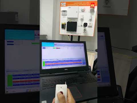
The same logic applies to third-party receivers. Receiver compatibility depends on the specific model, firmware, configuration, transport, account settings and event interpretation.
The qualification record should therefore say:
Tested with [specific receiver model/version/configuration] using [specific panel firmware/communicator firmware].
That statement contains far more engineering value than:
“Compatible with major CMS systems.”
13. Security Integration Beyond the Alarm Panel
Commercial intrusion systems increasingly sit inside broader security environments.
The panel may exchange events with video management systems, access control, building automation, security operations software or enterprise event platforms.
The integration mechanism might be a relay, dry contact, API, SDK, MQTT, Modbus or another interface.
The interface itself, however, is only one part of the engineering problem.
Alarm Panel and Video Management
The important chain is:
Intrusion Event
      ↓
Alarm Panel
      ↓
Integration Interface
      ↓
VMS / Camera
      ↓
Video Verification
      ↓
Operator Action
A relay output may be entirely appropriate for a simple event trigger. A documented API may be more appropriate where the operator needs structured events, camera selection or richer automation.
Athenalarm’s current AS-9000 documentation provides one manufacturer example in which alarm management software is integrated with CCTV functions for event-linked video verification, live video viewing and E-map positioning. That is useful as evidence of platform capability, but a project-specific deployment still needs validation against the exact VMS and software environment being used.
Alarm Panel and Access Control
The architectural question is often event ownership.
Does a forced-door event originate in the access-control system and inform the intrusion system?
Or is the alarm panel directly supervising a door-related input?
Those are different architectures, with different responsibility for event generation, event storage and event correlation.
Alarm Panel and Building Automation
HTTP/REST, MQTT and Modbus can all be useful integration methods, but a common protocol does not guarantee common semantics.
Modbus provides an exchange mechanism, but it does not define what an “intrusion verified” state means.
MQTT transports messages but does not, by itself, define event ownership.
An integration specification should therefore define data ownership, field definitions, authentication, versioning, command boundaries, failure behavior and backward compatibility.
The manufacturer should also be able to answer who owns the API specification and what happens to the interface when firmware changes.
Without that ownership, an API can become another form of vendor dependency.
14. Partitioning and Multi-Tenant Deployment
Multi-tenant commercial environments introduce another layer that is often underestimated during product selection.
An office tower, retail center or industrial park may require independent user permissions, schedules, partitions, event ownership and audit records.
The question is not simply whether the panel has “multiple partitions.”
A better question is:
Can Tenant A operate Tenant A’s security environment without unintentionally affecting Tenant B, while the monitoring center still retains an accurate event hierarchy?
That requires the partition structure to remain coherent across the panel, keypad, user database, event reporting and CMS.
For example, the qualification test should verify whether a tenant-specific disarm action remains attached to the correct account and partition, whether administrative override is logged, whether restore events retain the correct identity, and whether schedules and permissions remain independent.
Partitioning is therefore not merely a user-interface feature. It affects event semantics and central-monitoring operations.
When the deployment expands from a single facility to multiple sites, the architecture should preserve site identity, account identity, event identity, user identity, firmware traceability and receiver compatibility.
15. False Alarm Engineering Is an End-to-End Problem
False alarms are often discussed as if they were primarily detector problems.
In commercial monitoring, that is too narrow.
False-event sources can be grouped into five layers.
At the sensor layer, poor placement, environmental interference and unsuitable sensitivity can create false triggers.
At the wiring layer, intermittent circuits, damaged cables, unstable terminations and grounding problems can create unstable inputs.
At the panel-logic layer, inappropriate delay settings, filtering, event logic or partition behavior can create operational noise.
At the communication layer, retransmissions, incorrect failover handling and poorly designed supervision timers can make the same physical condition appear repeatedly or ambiguously at the CMS.
At the operator layer, incorrect account data, unclear workflows and insufficient verification can convert technical events into unnecessary operational responses.
This is why replacing detectors is not always the correct solution.
A system integrator can spend days changing sensors while the real problem is an event-mapping issue or a communication-retry configuration.
Event Correlation and Verification
A commercial monitoring workflow becomes more useful when it distinguishes:
Alarm
  ↓
Verification event
  ↓
Related video / access event
  ↓
Restore or follow-up event
  ↓
Operator action
Repeated transmission of the same physical event should not automatically become repeated incidents in the CMS.
The receiver and CMS should have clear handling for retries, duplicates, sequence and restoration.
SIA also maintains standards covering false-alarm reduction and monitoring practices, including ANSI/SIA CP-01-2019 and ANSI/SIA MSD-01-2000.
Communication Failure Is Not an Intrusion Event
This distinction deserves explicit treatment.
A communication fault means that the monitoring system may no longer have a valid communication path to the protected site.
An intrusion alarm means that the intrusion detection logic has produced an alarm event.
The two can occur together, but they are not operationally identical.
A CMS that turns every communication fault into an intrusion dispatch can create unnecessary response activity and reduce the quality of the monitoring workflow.
A well-defined system should therefore distinguish intrusion, tamper, AC failure, battery fault, communication fault, system trouble and restore conditions.
16. What Distributors and Integrators Should Demand from the Manufacturer
At this point, the manufacturer’s role becomes clearer.
The buyer is not simply purchasing the current hardware revision.
The buyer is potentially building an installed base around the supplier.
That makes firmware lifecycle, hardware revision policy and supply continuity part of the technical evaluation.
Firmware Is Part of the Product
A commercial panel should be evaluated for:
- firmware release policy;
- hardware-revision dependencies;
- backward compatibility;
- legacy-module support;
- update procedure;
- recovery procedure;
- release documentation;
- security or vulnerability-response process.
A panel can remain electrically available while becoming operationally difficult to support because an old programming tool, firmware branch or communication module has been discontinued.
That is why lifecycle documentation matters before the first large order rather than after an installed base already exists.
OEM and ODM Need a Written Boundary
OEM and ODM are often used interchangeably in international sales discussions, but procurement should define the engineering scope rather than rely on terminology.
A typical private-label OEM scope may include branding, labels, packaging, model numbering and standard hardware.
A deeper ODM scope may involve hardware changes, enclosure changes, firmware changes, communication-module changes or validation work.
Athenalarm currently documents OEM/ODM capabilities including private labeling, customized model names, wireless frequency configuration, firmware and language customization, communication-module configuration, packaging and technical-document customization.
Those published capabilities should be treated as manufacturer evidence. The buyer should still convert them into a project-specific engineering statement that defines who controls each revision and what happens when the standard product changes.
Long-Term Supply Risk Is More Than Production Capacity
A supplier may be capable of producing a thousand panels today.
That does not answer whether the next thousand will behave identically.
A proper qualification review should therefore address:
- component end-of-life;
- PCB revision policy;
- chipset substitutions;
- firmware compatibility;
- MOQ;
- lead time;
- spare parts;
- production continuity;
- quality-control documentation;
- revision notification.
The more useful supplier question is:
Can the manufacturer supply future production without silently changing the electrical, firmware, protocol or service characteristics on which the installed base depends?
17. Building a Distributor Product Portfolio Around a Platform
A distributor does not necessarily need a separate technical platform for every customer segment.
The stronger question is whether one hardware family can support several deployment classes while preserving a manageable support model.
A practical product-line structure might look like this:
| Segment | Typical architecture | Communication | Deployment |
|---|---|---|---|
| Entry | Conventional or compact | IP/cellular | Small sites |
| Commercial | Hybrid / bus expansion | Multi-path | Medium commercial sites |
| Enterprise | Expandable / networked | Multi-path + CMS | Multi-site environments |
The exact segmentation should follow the manufacturer’s actual product architecture, regulatory requirements and target market.
The more important portfolio question is SKU commonality.
Can the distributor reuse:
- the same main panel family;
- common keypads;
- shared expansion modules;
- common communication modules;
- common detectors;
- common accessories;
- common firmware infrastructure?
A platform strategy can reduce inventory and training complexity, but it should not be confused with a “one SKU for everything” strategy.
Regional differences may require different wireless frequencies, telecom bands, mains requirements, certification configurations, labels, languages or enclosures.
A well-designed architecture aims for:
Common Core Platform
        ↓
Regional Communication Options
        ↓
Market-Specific Variants
        ↓
Different Capacity Levels
        ↓
Different OEM Brands
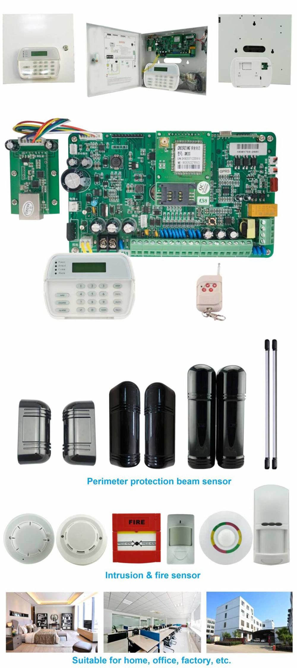
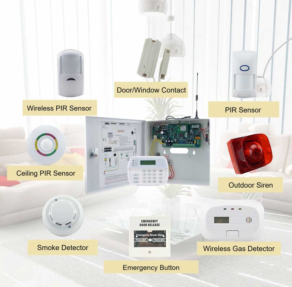
Athenalarm’s AS-9000 family is one example of this platform-oriented approach. Its published architecture combines onboard wired and wireless inputs with RS-485 addressable expansion and different communication configurations, including Ethernet, 4G LTE and PSTN depending on model. See the published AS-9000 product documentation for the manufacturer evidence.
That information is useful as manufacturer evidence. It should still be confirmed against the exact configuration being procured.
18. A Practical Engineering Procurement Process
Supplier approval is more reliable when it follows engineering gates instead of a single quotation review.
Define the Deployment Architecture
Before asking manufacturers for a final proposal, define the building type, site size, zone count, module count, cable distances, network environment, CMS location, required redundancy and regional telecom conditions.
Define Zone and Expansion Requirements
Specify not only the final zone count but how those zones will be implemented.
Document onboard zones, wireless capacity, addressable expansion, partitions, expansion modules and expected future growth.
Calculate Power and Bus Requirements
Calculate panel current, remote-device current, communicator load, alarm-state load, battery requirement, cable resistance, voltage drop and bus loading.
For long runs, the farthest device should be evaluated under the worst realistic connected load.
Define Communication Redundancy
Specify primary and secondary paths, failure detection, heartbeat, timeout, acknowledgement, retry, reconnection and offline reporting.
Then determine whether the two communication paths are genuinely independent.
Define the CMS Receiver
Specify the receiver model, receiver firmware, protocol, transport, encryption, account configuration, event mapping, ACK behavior and supervision requirements.
“CMS compatible” is not a specification.
Validate Third-Party Integration
Where required, test VMS, access control, BAS, APIs, relay interfaces and SDKs using the actual project environment.
A theoretical protocol match is not sufficient.
Audit Firmware and Lifecycle Policy
Request revision history, update procedures, hardware compatibility, legacy-support policy and vulnerability-response procedures before approving the first significant production order.
Freeze OEM/ODM Scope
Define branding, enclosure, label, model, frequency, communication module, firmware, language, packaging, manuals, testing, MOQ and change-control requirements.
Conduct Field Interoperability Testing
At minimum, simulate primary-path failure, cellular failure, receiver restart, ACK timeout, panel reboot, low battery, AC failure, RS-485 module removal, communication interference and repeated events.
Approve the Manufacturer as a Platform
The final qualification file should connect the commercial decision to technical evidence:
Technical Specification
        +
Protocol Evidence
        +
CMS Test Record
        +
Field Test Results
        +
Firmware Policy
        +
OEM Specification
        +
Supply Continuity Review
That is the difference between approving a product and approving a manufacturer platform.
19. Commercial Alarm Panel Manufacturer Qualification Matrix
The following matrix is deliberately organized around evidence rather than marketing claims.
| Evaluation area | Requirement | Evidence to request | Validation |
|---|---|---|---|
| Physical | Zone architecture | Datasheet + installation manual | Field test |
| Physical | RS-485 topology | Wiring specification | Field test |
| Physical | Bus loading | Engineering documentation | Calculation + test |
| Power | Auxiliary capacity | PSU specification | Load test |
| Power | Battery backup | Calculation method | Load/backup test |
| Communication | Ethernet | Interface specification | Transmission test |
| Communication | 4G LTE | Module documentation | Cellular test |
| Communication | Failover | State logic | Failure/recovery test |
| Protocol | SIA DC-09 | Exact revision + implementation evidence | Receiver test |
| Protocol | Contact ID | Protocol declaration | Receiver test where required |
| CMS | Receiver compatibility | Specific integration record | End-to-end test |
| CMS | Event mapping | Event matrix | Event test |
| Integration | API | API documentation | Interface test |
| Firmware | Lifecycle | Release policy | Documentation audit |
| OEM | Customization scope | OEM specification | Sample / approval |
| Supply | MOQ and lead time | Commercial quotation | Procurement review |
| Support | Technical support | Support process | Escalation test / service review |
A useful supplier-audit rule is simple:
Every important specification should have either documentary evidence, calculation evidence, test evidence, or a clearly defined project assumption.
20. Field Troubleshooting: Diagnose the Layer Before Replacing the Hardware
The value of a mature alarm platform is visible when something goes wrong.
A useful troubleshooting method is to isolate the failure layer first.
Panel Is Online but CMS Receives No Alarm
Start with the event itself.
Alarm Generated
      ↓
Panel Event Logged?
      ↓
Communication Path Active?
      ↓
Receiver Received?
      ↓
Event Parsed Correctly?
      ↓
CMS Operator Display Correct?
If the panel logs the event correctly, the detector and primary alarm logic may already be functioning.
The investigation then moves upward into communicator configuration, transport, destination, firewall, receiver configuration, account provisioning, protocol handling and acknowledgement.
This method is more efficient than replacing the panel immediately.
RS-485 Device Goes Offline Intermittently
A practical sequence is:
Power → wiring → topology → termination → addressing → EMI → device
The field mistake to avoid is replacing the module before checking the actual voltage at the module under operating load.
If the far-end voltage collapses when additional devices activate, changing the module does not solve the underlying problem.
CMS Receives the Event but the Zone Is Wrong
That is often an integration problem rather than a detection problem.
Check:
- panel address assignment;
- module addressing;
- account configuration;
- event mapping;
- zone conversion;
- receiver interpretation.
IP Fails but Cellular Failover Does Not Occur
Test the layers separately:
Ethernet Link
   ↓
IP Connectivity
   ↓
Application Session
   ↓
Heartbeat
   ↓
Timeout
   ↓
Failover Trigger
   ↓
Cellular Registration
   ↓
Cellular Session
   ↓
Receiver ACK
An Ethernet interface can remain physically active while the application session is dead.
Likewise, a cellular modem can be registered to the carrier and still fail to establish the required alarm-reporting session.
Receiver ACK Is Missing
If the sender transmits correctly but does not receive the expected acknowledgement, it may repeatedly retransmit the event.
Investigate the receiver profile, destination, encryption settings, account configuration, message handling, receiver logs, return network path and firmware compatibility.
Duplicate Events Appear in the CMS
Possible causes include event retransmission, lost ACKs, receiver processing delay, failover overlap and reconnect behavior.
The system should distinguish:
new event → retry → duplicate delivery → restore
rather than treating every received transmission as a new physical alarm.
21. Technical FAQ for Commercial Alarm Panel Procurement
What should you look for when evaluating an alarm panel manufacturer?
Evaluate the complete platform: physical architecture, power, communication paths, protocols, CMS interoperability, firmware lifecycle, OEM capability and supply continuity. Require documented evidence and project-specific testing rather than relying only on the datasheet.
What makes an RS-485 alarm panel suitable for large commercial deployments?
The manufacturer should document bus topology, device addressing, maximum loading, cable assumptions, power distribution, termination, diagnostics and expansion architecture. Large-site suitability depends on the complete electrical design, not the presence of an RS-485 interface alone.
How do you calculate voltage drop on an alarm bus?
Use (V_{drop}=I\times R), where resistance depends on conductor material, gauge and total electrical path length. For two-wire DC power, use the round-trip conductor length and verify voltage at the farthest device under maximum expected load.
What is the difference between SIA DC-09 and Contact ID?
SIA DC-09 is an IP event-reporting standard designed for communication between premises equipment and central stations. Contact ID is a separate alarm communication format documented by SIA as DC-05. Legacy event formats may still be required when integrating with existing monitoring infrastructure.
Why does CMS receiver interoperability matter?
Because successful alarm transmission depends on the entire path: panel, communicator, network, receiver, protocol parser, account configuration, acknowledgement and CMS event interpretation. A protocol claim by itself does not prove end-to-end compatibility.
How should Ethernet and 4G LTE failover be engineered?
Define exactly what constitutes a communication failure and document the timeout, supervision, failover, acknowledgement, retry and restoration behavior. Two interfaces should not automatically be assumed to provide independent paths.
How can a distributor evaluate alarm-panel firmware lifecycle risk?
Request firmware revision history, supported hardware revisions, compatibility policy, update procedure, recovery procedure, legacy support and security-response policy. The goal is to protect the installed base from becoming dependent on an obsolete hardware or firmware branch.
What should be included in an OEM alarm panel specification?
Define branding, enclosure, model numbering, labels, wireless frequency, communication modules, firmware behavior, language, packaging, documentation, testing, MOQ, lead time, revision control and post-production support.
How should alarm panels integrate with VMS, access control and BAS?
Define the event owner, communication interface, data structure, authentication, command boundaries, versioning, failure handling and backward compatibility. Simple relay integration and deeper API-based integration solve different operational problems.
What should be tested before approving a new alarm panel manufacturer?
Test actual alarm and restore events, power faults, battery faults, RS-485 failures, primary-path failure, secondary-path failover, receiver acknowledgement, event mapping, duplicate handling, restart behavior and the target CMS configuration.
22. Manufacturer Qualification Checklist
A useful qualification process ends with a checklist that can be used by engineering, procurement and management together.
Hardware
Zone architecture should be documented. RS-485 topology and maximum loading should be defined. Power budget and backup behavior should be documented. Protection and expansion architecture should be understood.
Communication
Ethernet and cellular paths should be tested where applicable. Failover should be demonstrated rather than claimed. Heartbeat, timeout, ACK, retry and reconnection behavior should be documented.
Protocol
The exact SIA DC-09 revision should be identified where applicable. Contact ID support should be verified when required by the target CMS. Encryption and event mapping should be documented.
CMS
The actual receiver configuration should be tested. Alarm, restore, communication loss, AC failure, battery failure, failover, duplicate events and ACK timeout should all be included in the integration record.
Integration
Required VMS, access-control and BAS interfaces should be tested against the actual project environment. API ownership, authentication and versioning should be documented.
Firmware
Release policy, hardware compatibility, backward compatibility, upgrade procedure, recovery procedure and security-response procedures should be documented.
Commercial
OEM/ODM scope, MOQ, lead time, spare-parts policy, technical support and production continuity should be reviewed before long-term procurement approval.
23. How to Turn a Datasheet into a Procurement Specification
The clearest sign of a mature procurement process is that vague marketing language disappears from the final specification.
A weak requirement says:
“Alarm panel shall support RS-485, 4G and SIA.”
A stronger requirement says:
The manufacturer shall provide documented RS-485 topology, maximum device loading, cable requirements, power-distribution requirements, termination requirements and diagnostic behavior. The selected system shall be tested under the project topology and maximum connected load.
A weak communication requirement says:
“Dual-path communication required.”
A stronger one says:
The communicator shall support defined primary and secondary transmission paths. The manufacturer shall document failure detection, supervision, acknowledgement, retransmission, path transition and restoration behavior. Primary-path failure and recovery shall be demonstrated under field-test conditions.
A weak CMS requirement says:
“Compatible with CMS.”
A stronger one says:
The selected panel and communicator shall be tested against the specified CMS receiver configuration. Alarm, restore, zone, partition, AC-loss, battery-fault, communication-loss, failover, ACK-timeout and duplicate-event behavior shall be recorded in an interoperability test report.
This is the difference between purchasing features and purchasing an engineered platform.
24. A Manufacturer Evidence Example: Evaluating the Athenalarm AS-9000
The same framework can be applied to Athenalarm or any other commercial alarm panel manufacturer.
The important discipline is to separate manufacturer evidence from buyer validation.
Athenalarm’s published AS-9000 documentation identifies an RS-485 addressable architecture, up to 1,656 addressable zones, 16 onboard wired zones, 30 wireless zones, and TCP/IP, 4G LTE and PSTN communication configurations depending on model. The published product information also describes AS-ALARM network alarm-center software, event logging, CCTV/video-verification functions and OEM/ODM customization.
The same product documentation identifies a 32-bit ARM processor, approximately 1,500 event records, power monitoring, backup battery management, tamper monitoring and surge protection.
These are useful manufacturer evidence points.
They should then be translated into validation activities.
If RS-485 expansion is specified, the integrator should validate the actual project topology, cable and far-end power conditions.
If 1,656 addressable zones are part of the project discussion, the buyer should establish how those zones are physically distributed, how many modules are required and how addressing and power are implemented.
If TCP/IP, 4G LTE and PSTN are offered, the buyer should test the communication path required by the target market rather than assuming that the presence of three interfaces automatically constitutes a fully independent multi-path architecture.
If network alarm-center software is used, the actual CMS workflow should be tested.
If CCTV integration is required, the target VMS environment should be tested.
If firmware customization is required for an OEM project, the revision-control and maintenance responsibilities should be documented before production.
The principle is straightforward:
A datasheet is evidence of what a manufacturer says its platform supports. A qualification test is evidence that the specific project configuration works.
That distinction should be applied equally to Athenalarm and to competing manufacturers.
25. Final Engineering Perspective
A commercial intrusion alarm panel manufacturer should ultimately be evaluated across the complete operating chain:
Sensors
  ↓
Zones / RS-485 Bus
  ↓
Alarm Control Panel
  ↓
Power Architecture
  ↓
Communication Module
  ↓
Ethernet / Cellular / Legacy Path
  ↓
Alarm Transmission Protocol
  ↓
Receiver
  ↓
CMS / ARC
  ↓
Operator Workflow
  ↓
Video / Access / Building Integration
A failure at any interface can defeat an otherwise capable panel.
The most useful procurement model is therefore not a feature checklist. It is an evidence chain:
physical integrity → power margin → bus integrity → communication resilience → protocol compliance → receiver interoperability → integration ownership → firmware lifecycle → supply continuity
That approach also changes the way a distributor should think about manufacturer comparison.
Unit price still matters. Zone capacity still matters. MOQ, lead time and OEM capability still matter.
But none of those variables exists independently of engineering support.
A low-cost panel that requires excessive field troubleshooting may create a higher total cost after installation. A panel with a large theoretical zone count may become difficult to deploy if its bus-loading assumptions are unclear. A communicator with multiple interfaces may still have limited resilience if the paths share too many common failure points. A protocol listed on the datasheet may still require engineering work if the target receiver interprets events differently.
This is why commercial alarm panel procurement should move from feature comparison to evidence-based platform qualification.
The strongest manufacturer qualification file should allow an engineering team to answer five questions without relying on sales interpretation:
How is the field network engineered?
How does the alarm event travel to the monitoring center?
What happens when each important communication layer fails?
Has the actual CMS receiver configuration been tested?
Can the manufacturer support the same technical behavior across future production and firmware revisions?
When those questions can be answered with documentation, calculations and repeatable field tests, the alarm panel becomes more than a hardware product.
It becomes a deployable platform.
For distributors, importers, OEM brand owners and security system integrators, that is the level at which long-term procurement decisions should be made: not by the number of features printed on the box, but by the degree to which the manufacturer can provide predictable engineering behavior from the protected site to the monitoring center and throughout the lifecycle of the installed base.